Expertly designed control rooms integrating ergonomics, safety, and efficiency for optimal operator performance and seamless workflow.
Over the past 8 years, we’ve designed and engineered over 150 control rooms, earning us the industry nickname “Control Room Guys.” This experience empowers us to deliver precision-engineered, human-centered control room solutions.
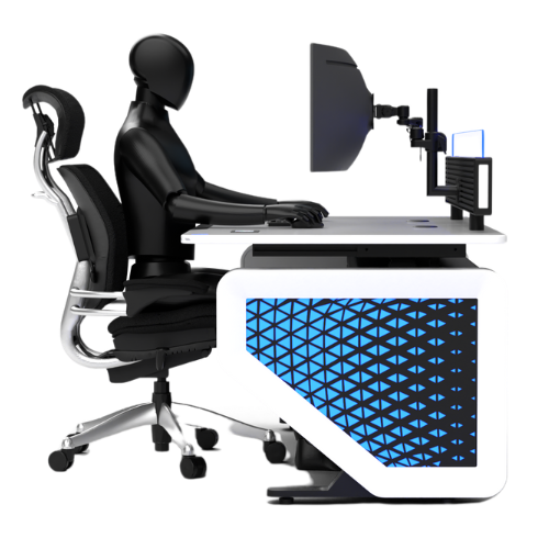
Every control room is unique—governed by its Human-Machine Interface (HMI) needs. Our solutions are tailored to optimize operator comfort, functionality, and alertness, which are critical for mission-critical environments.
We focus on how control room operators interact with machines and the environment. Our ergonomics-driven designs prioritize:
The shape and configuration of consoles are selected based on the scale and layout of video walls:
Example Layout:
This hierarchy ensures optimal sightlines and ergonomic balance for all operators.
At the concept stage, requirements and inputs from all stakeholders must be incorporated for effective design. Workflow considerations are categorized into the following major groups:
The location of the control room is influenced by non-Human Factors Engineering (non-HFE) considerations such as:
Structural Design Considerations:
Space allocation for the Control Room should consider the following:
Space planning should be tailored based on specific project requirements.
The layout should integrate Human Factors Engineering (HFE) principles, including:
All these aspects collectively define the layout and general arrangement of the Central Control Room (CCR), ensuring operational efficiency, safety, and comfort.
A control room is a task-critical environment where operators monitor and control various system activities. This work demands high levels of concentration and focus, which can be severely impacted by sound disturbances.
Contrary to popular belief, acoustic quality is not defined by materials alone, but by the detailing that controls reverberations, resonances, and reflections.
To ensure effective sound control, multiple disciplines of acoustics are taken into account:
Key considerations for console layout include:
When selecting materials and finishes for the control room environment, multiple factors must be considered to ensure functionality, comfort, and visual harmony.
Proper lighting is essential in a control room environment — not only to support operational tasks but also to reduce fatigue, enhance focus, and contribute to a calm and productive atmosphere.
The readability of screens and display walls is directly influenced by:
All these parameters are balanced to ensure optimal onscreen contrast and clarity for both close and distant viewing.
In a mission-critical control room, uninterrupted focus and minimal distractions are essential for effective operation. Every movement within the space—whether by operators or visitors—must be deliberately planned to prevent interference with workflow and concentration.
Human Factors Engineering (HFE) is critical to designing control rooms that support operator comfort, efficiency, and safety—especially in 24/7 mission-critical environments. Every aspect of the design must optimize the interaction between humans and their work environment.
HFE is applied across various parameters to support performance and health:
Fill in your details and our team will get back to you shortly.